
Teach
With Bigshot |
Dynamo
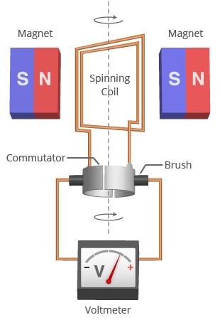
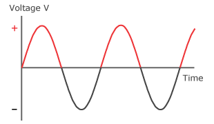
A dynamo is a device that converts mechanical energy into electrical energy. Figure 5 shows the structure of a simple dynamo. A coil made of conducting wire is positioned between the North and South poles of two permanent magnets. When the coil is stationary, no voltage is induced. But when the coil is rotated it experiences a changing magnetic field. This induces a voltage within the coil. For the first half of a rotation the left side of the coil swings by the North pole of the left magnet and for the second half of the rotation it swings by the South pole of the right magnet. As a result, for the first half the coil generates a voltage with one polarity (either positive or negative) and for the second half the voltage has the opposite polarity. This type of voltage − one that switches between positive and negative − is called alternating voltage. Figure 6a shows the typical sinusoidal-shaped alternating voltage generated in the dynamo coil. The height of the sinusoidal wave, which represents the strength of the voltage induced in the coil, depends on the strength of the magnetic field, the number of loops in the coil, and the speed at which the coil rotates [1]. The spinning coil of the dynamo is connected to the circuit that it powers using a commutator [2]. The commutator consists of two half-cylinders of smooth conducting material that are separated by a small gap. Each half-cylinder is permanently attached to one end of the rotating coil, and the commutator rotates with the coil. Two stationary brushes, usually made of carbon, press against the spinning commutator. The brushes act as the terminals (outputs) of the dynamo.
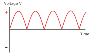
In addition to acting as the terminals of the electricity-generating coil, the commutator performs another very important function. It keeps the dynamo's generated voltage from alternating between positive and negative. Each brush slides along the two halves of the commutator, switching halves the instant the voltage in the coil reverses polarity. This ensures that the voltage produced by the dynamo is no longer fluctuating between positive and negative, but is instead always positive. This type of voltage is called direct voltage, and is shown by the curve in Figure 6b. This process, where alternating voltage is converted to direct voltage, is called rectification [3].
|


 References
| [1] | C. S. Siskind, Electrical machines, direct and alternating current. McGraw-Hill, 1950. |
| [2] | "Commutator." Wikipedia, The Free Encyclopedia. [Online]. Available: http://en.wikipedia.org/wiki/Commutator_(electric). [Accessed: Jun 3, 2012]. |
| [3] | "Rectifier." Wikipedia, The Free Encyclopedia. [Online]. Available: http://en.wikipedia.org/wiki/Rectifier. [Accessed: Jun 3, 2012]. |
